- About Us
- News
-
Products
- All
- Electric Built-in Guideway Servo Actuator (AU)

- Electric Linear Actuator (JD)

- Electric Cylinder/Mini Linear Actuator (JDR)

- Multi-axis CCD Alignment Stage (XYY)

- Linear motor module/ Optical measuring systems/ Rotor and Stator

- Hollow Rotating Platform (DZ)

- Electric Micro Stage (XBK)

- Manual Micro Stage

- Closed Loop Stepping System (UT)

- Desktop Automatic Locking-screw Machine

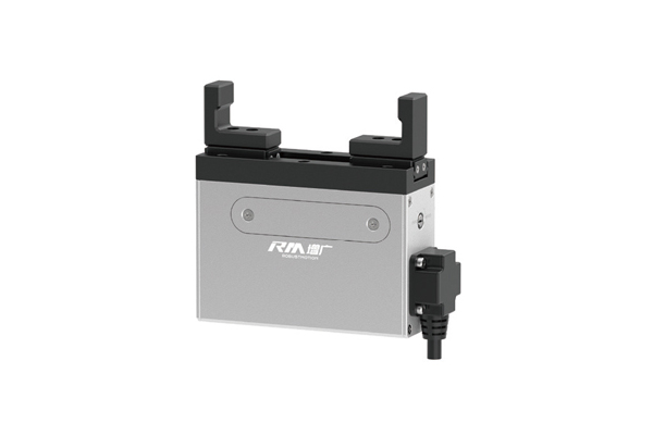
- Electric gripper

-
Application
- 5G Component Manufacturer

- Automobile & Electric Vehicle Component Manufacturer

- FDP Manufacturing

- Wafer Manufacturer

- Lens Optics Manufacturer

- Smartphone Component Manufacturer

- LED Manufacturer

- Solar Energy Manufacturer

- PCB Board Manufacturer
- Precision Screen Printing Manufacturer

- Polarizer Laminator Manufacturer

- Glass Substrate Bonding Manufacturer

- 5G Component Manufacturer
- Supports
- E-Catalogue
- Video
-
Download
- Standard Built-in Guideway Ball Screw Servo Actuator-AU
- Clean Room Built-in Guideway Ball Screw Servo Actuator-AUS
- Standard Built-in Guideway Belt Servo Actuator-AUT
- Clean Room Built-in Guideway Belt Servo Actuator-AUTS
- Standard Ball Screw Driven Actuator-JDB
- Clean Room Ball Screw Driven Actuator-JDBS
- Standard Belt Driven Actuator-JDT
- Clean Room Belt Driven Actuator-JDTS
- Electric Cylinder/Electric Micro Putter-JDRN/JDRM
- Multi-axis CCD Alignment Stage-XYY
- Linear Motor Robot-JDLM
- Electric Mirco Stage-XBK
- Electric Gripper
- Contact Us
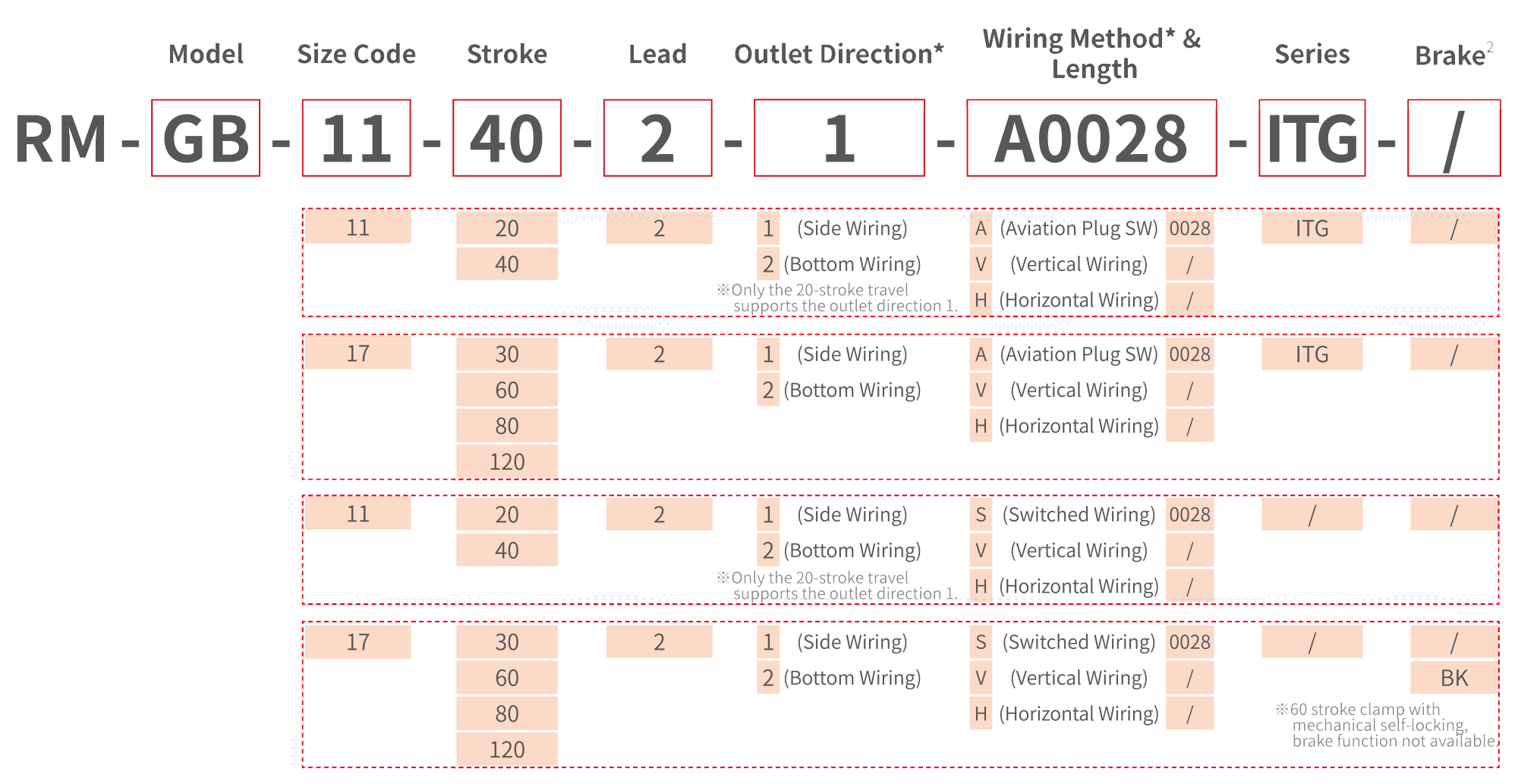
ITG Integrated (Built-in Controller)
| Item | Parameters | |||||||
|---|---|---|---|---|---|---|---|---|
| Model Description | Model | RM-GB-11-20-2-ITG | RM-GB-11-40-2-ITG | RM-GB-17-30-2-ITG | RM-GB-17-60-2-ITG | RM-GB-17-80-2-ITG | RM-GB-17-120-2-ITG | |
| Size Code | 11 | 11 | 17 | 17 | 17 | 17 | ||
| Stroke(mm) | 20 | 40 | 30 | 60 | 80 | 120 | ||
| Type Code | 2 | 2 | 2 | 2 | 2 | 2 | ||
| Performance | Max.gripping Force'1(N) | 65 | 110 | 350 | 175 | 500 | 500 | |
| Max.speed(mm/s) | 80 | 80 | 80 | 80 | 80 | 80 | ||
| Repeat Positioning Accuracy(mm) | ±0.05 | ±0.05 | ±0.05 | ±0.05 | ±0.02 | ±0.02 | ||
| Max.opening/closing Time(s) | 0.33/0.33 | 0.58/0.58 | 0.4/0.4 | 0.7/0.7 | 0.9/0.9 | 1.3/1.3 | ||
| Permissible Load Torque(N.m) | MR: 8.0 MP: 5.9 MY: 5.9 |
MR: 8.0 MP: 5.9 MY: 5.9 |
MR: 58.5 MP: 15.0 MY: 25.5 |
MR: 58.5 MP: 15.0 MY: 25.5 |
MR: 60 MP: 30 MY: 40 |
MR: 60 MP: 30 MY: 40 |
||
| Power Failure Auto-Lock | Mechanical Self-Locking | Mechanical Self-Locking | / | Mechanical Self-Locking | / | / | ||
| Control Method | Control Method | Bus | Modbus RTU/CANopen | Modbus RTU/CANopen | Modbus RTU/CANopen | Modbus RTU/CANopen | Modbus RTU/CANopen | Modbus RTU/CANopen |
| Interface | I/O | I/O | I/O | I/O | I/O | I/O | ||
| I/O Interface | Input 3 Points(NPN) Output 3 Points(NPN) |
Input 3 Points(NPN) Output 3 Points(NPN) |
Input 2 Points(NPN) Output 3 Points(NPN) |
Input 2 Points(NPN) Output 3 Points(NPN) |
Input 2 Points(NPN) Output 3 Points(NPN) |
Input 2 Points(NPN) Output 3 Points(NPN) |
||
| Operating Environment | Rated Voltage(V) | DC24±10% | DC24±10% | DC24±10% | DC24±10% | DC24±10% | DC24±10% | |
| Rated Current(A) | 2 | 2 | 4 | 4 | 4 | 4 | ||
| Weight(kg) | 0.8 | 1.1 | 2.1 | 2.3 | 3.45 | 3.6 | ||
| Usage Environment | 0~40°C<85%RH (Without condensation) | |||||||
| Protection Class IP | IP40 | IP40 | IP40 | IP40 | IP40 | IP40 | ||
Split Type Model (External Controller)
| Item | Parameters | |||||||
|---|---|---|---|---|---|---|---|---|
| Model Description | Model | RM-GB-11-20-2 | RM-GB-11-40-2 | RM-GB-17-30-2 | RM-GB-17-60-2 | RM-GB-17-80-2 | RM-GB-17-120-2 | |
| Size Code | 11 | 11 | 17 | 17 | 17 | 17 | ||
| Stroke(mm) | 20 | 40 | 30 | 60 | 80 | 120 | ||
| Type Code | 2 | 2 | 2 | 2 | 2 | 2 | ||
| Performance | Max.gripping Force1(N) | 65 | 110 | 500 | 250 | 700 | 700 | |
| Max.speed(mm/s) | 80 | 80 | 80 | 80 | 80 | 80 | ||
| Repeat Positioning Accuracy(mm) | ±0.05 | ±0.05 | ±0.02 | ±0.05 | ±0.02 | ±0.02 | ||
| Max.opening/closing Time(s) | 0.33/0.33 | 0.58/0.58 | 0.4/0.4 | 0.7/0.7 | 0.9/0.9 | 1.3/1.3 | ||
| Permissible Load Torque(N.m) | MR: 8.0 MP: 5.9 MY: 5.9 |
MR: 8.0 MP: 5.9 MY: 5.9 |
MR: 58.5 MP: 15.0 MY: 25.5 |
MR: 58.5 MP: 15.0 MY: 25.5 |
MR: 60 MP: 30 MY: 40 |
MR: 60, MP: 30 MY: 40 |
||
| Power Failure Auto-Lock | Mechanical Self-Locking | Mechanical Self-Locking | Optional Brake | Mechanical Self-Locking | Optional Brake | Optional Brake | ||
| Control Method | Compatible Controllers | RM-C-20, RM-CEP-20, RM-CEM |
RM-C-20, RM-CEP-20, RM-CEM |
RM-C-40, RM-CEP-40, RM-CEM |
RM-C-40, RM-CEP-40, RM-CEM |
RM-C-40, RM-CEP-40, RM-CEM |
RM-C-40, RM-CEP-40, RM-CEM |
|
| Supporting Bus Protocols | Modbus RTU, EtherCAT, Modbus TCP, PROFINET, EtherNet/IP, CC-LINK, CANopen | |||||||
| Operating Environment | Rated Voltage(V) | DC24±10% | DC24±10% | DC24±10% | DC24±10% | DC24±10% | DC24±10% | |
| Rated Current(A) | 2 | 2 | 4 | 4 | 4 | 4 | ||
| Weight(kg) | 0.8 | 1.1 | 2.1 | 2.3 | 3.45 | 3.6 | ||
| Usage Environment | 0~40°C<85%RH (Without condensation) | |||||||
| Protection Class IP | IP40 | IP40 | IP40 | IP40 | IP40 | IP40 | ||
Notes:
1. The data is sourced from the actual test results in the 25°C laboratory.
2. The drawings provided in this Catalogue are for the default standard model. If you require other models with different motor directions, outlet directions, or outlet methods, please contact your local sales representative to obtain the drawings for the optional models.
RM-GB-11-20/40 & RM-GB-11-20/40-ITG
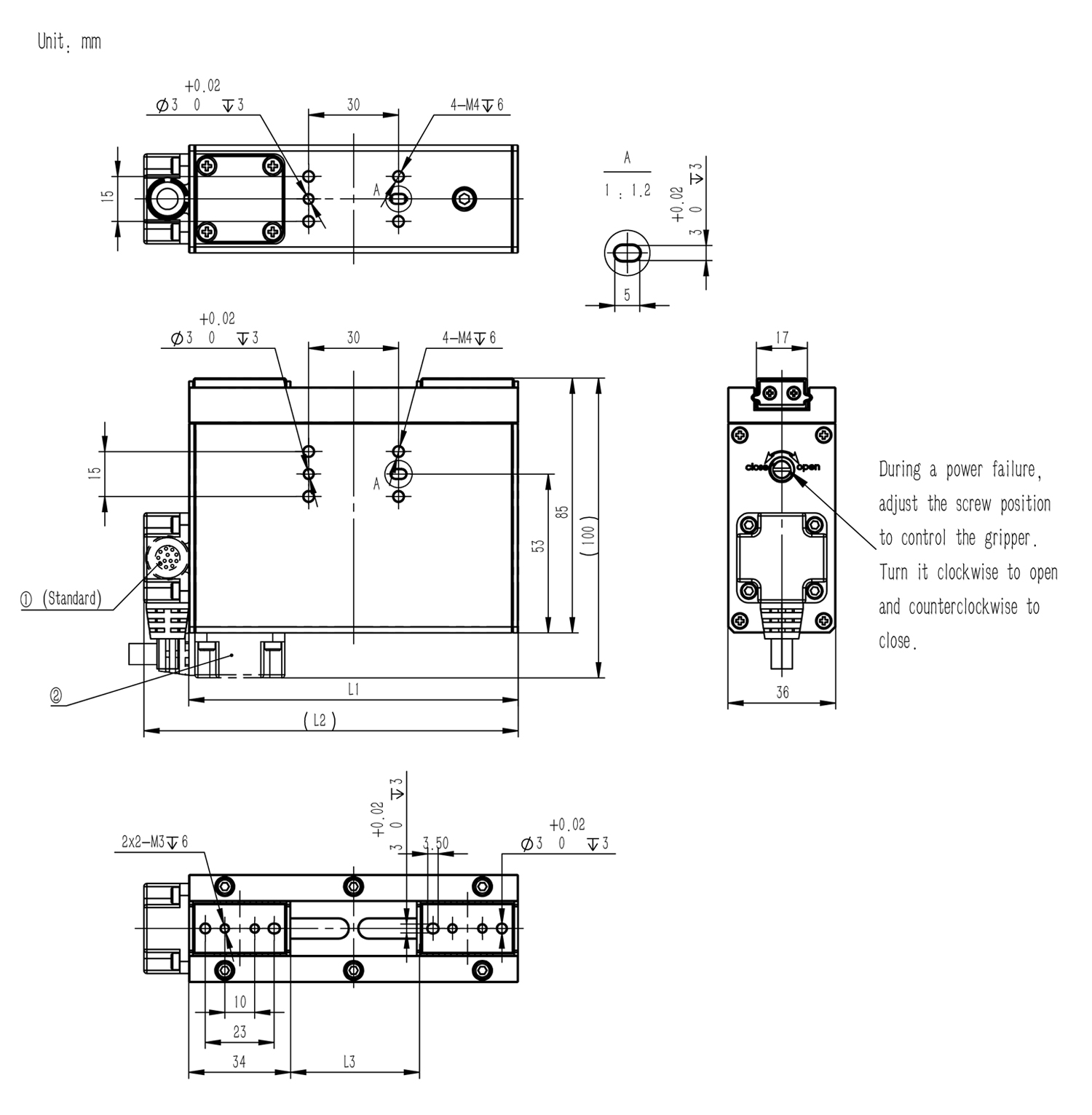
Installation Instructions:
1. When fixing the main body, please use all the screws on the same installation surface.
2. When tightening the bolts, do not exceed the depth of the threaded hole.
3. Wiring positions ( ① and ② ) are available (the default is①). Grippers with a stroke of 20mm have only one available wiring position, which is ①.
| Stoke | 20 | 40 |
|---|---|---|
| L1 | 90 | 110 |
| L2 | 105 | 125 |
| L3 | 0~20 | 0~40 |
RM-GB-11-30/60 & RM-GB-11-30/60-ITG
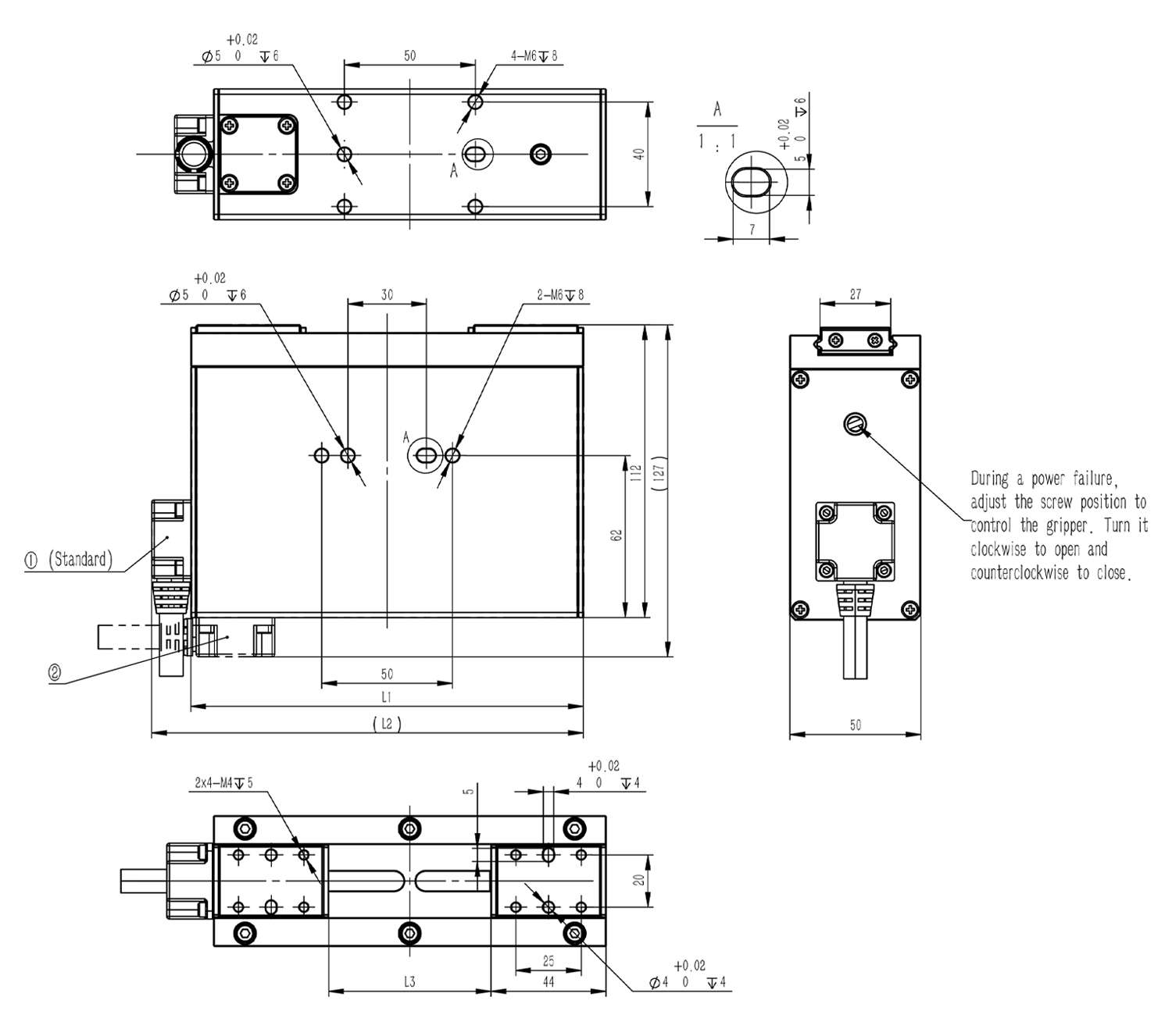
Installation Instructions:
1. When fixing the main body, please use all the screws on the same installation surface.
2. When tightening the bolts, do not exceed the depth of the threaded hole.
3. Wiring positions ( ① and ② ) are available (the default is①). Grippers with a stroke of 20mm have only one available wiring position, which is ①.
| Stoke | 30 | 60 |
|---|---|---|
| L1 | 150 | 150 |
| L2 | 165 | 165 |
| L3 | 32~62 | 0~60 |
RM-GB-11-80/120 & RM-GB-11-80/120-ITG
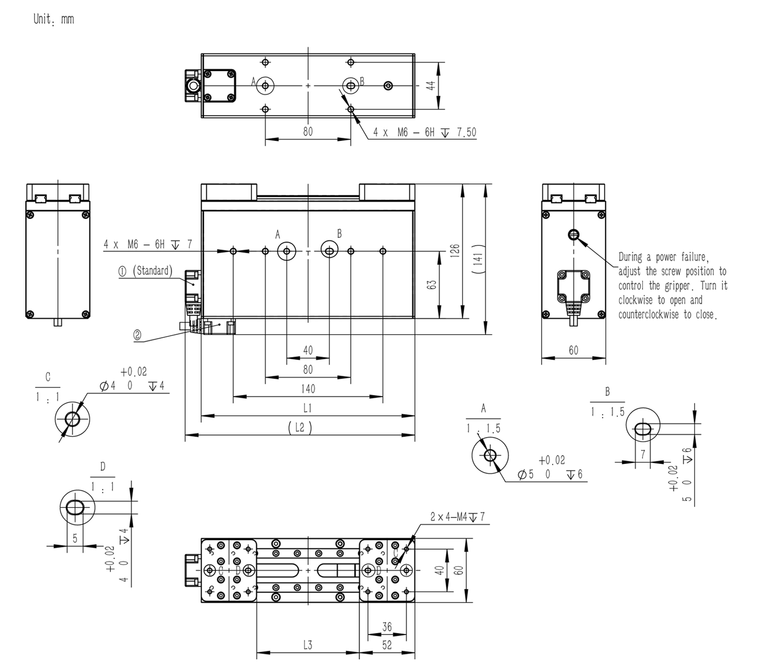
Installation Instructions:
1. When fixing the main body, please use all the screws on the same installation surface.
2. When tightening the bolts, do not exceed the depth of the threaded hole.
3. Wiring positions ( ① and ② ) are available (the default is①). Grippers with a stroke of 20mm have only one available wiring position, which is ①.
| Stoke | 80 | 120 |
|---|---|---|
| L1 | 200 | 240 |
| L2 | 215 | 255 |
| L3 | 16~96 | 16~136 |

